List of my modules...
Module: Skeletonise
Description:
Skeletonises the object. Uses a sequential homotopic thinning algorithm, you can provide a priority image to define the order in which the thinning is performed (such as distance-ordered if the distance map is set as priority). You can also provide a image of anchor or undeletable pixels (such as a medial axis).
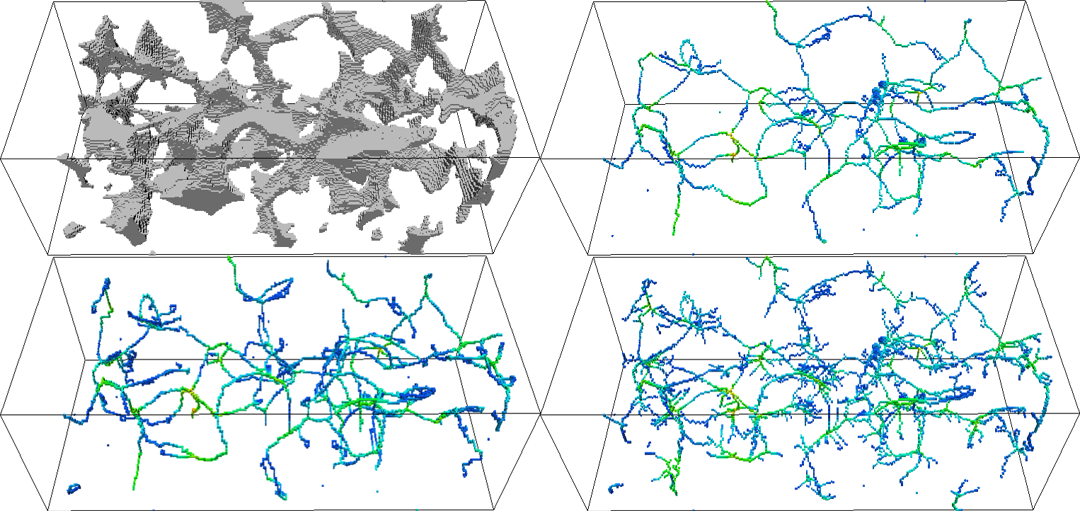
Top left:Initial object. Top right: resulting 26-connected ultimate skeleton. Bottom left: 6-connected ultimate skeleton. Bottom right: 26-connected non-ultimate skeleton (dead-endsare kept).
Notes
- At first glance, the boundary conditions object and mirror might seem to do the same thing (keeping connections to the image border), but there's at least one difference: mirror will preserve connections with specific borders. See for instance the example in the figure below: since with object boundary condition the entire exterior is supposed to belong to the object, the entire lower part of this object will be thinned, while in mirror mode the last pixel on the edge of the bounding box during the tinning process will be simple, and thus be kept along with the lower portion.
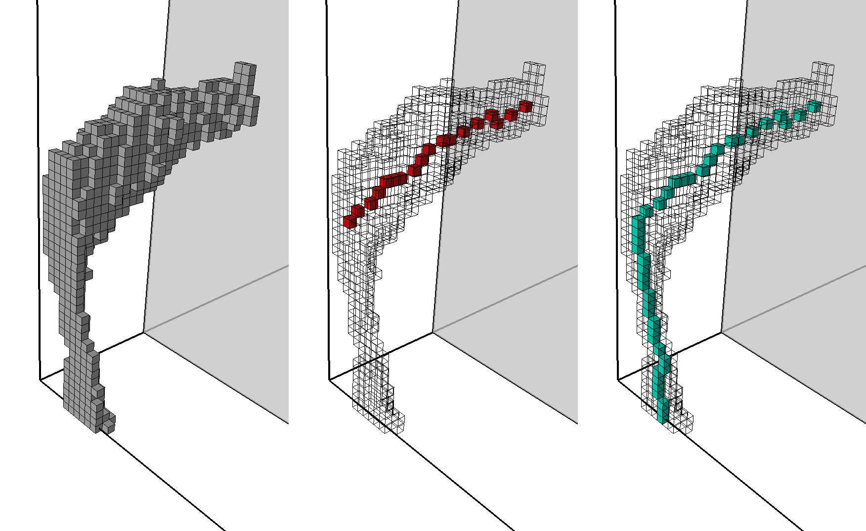
Illustration of the difference between boundary conditions. Left: lower portion of an object that is skeletonised, drawn with the Draw_Cubes module. The black lines show the bounding box of the image, while the transparent grey plane shows where the rest of the object was cut for visualisation purposes. The center image shows, with the original object in wireframe, the resulting portion of the skeleton when using object boundary condition, and the right image is with the mirror boundary condition.
Connections:
Data
[required]
The input image, of type HxUniformScalarField3 comes in through this port.
Priority
[optional]
The priority image, of type HxUniformScalarField3. Without this image, the skeleton might not be centred in the object, or even topological "knots" will result (like Bing's house), instead of nice clean 1D branches.
Anchor
[optional]
Pixels that cannot be thinned, of type HxUniformScalarField3.
Ports:
Threshold

Used to define, along with the comparison operator, which pixels are in the object.
Comparison

Used to define how the threshold value is used for defining the object.
Threshold_anchor

Defines in Anchor image which pixels are anchors.
Comparison_anchor

Associated comparison function for the anchor image.
Connectivity
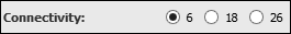
Connectedness of the skeleton. If you don't have a good reason for something else, you should choose 26-connectivity as it produces skeletons with fewer pixels.
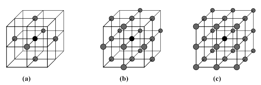
Illustration of the different connectivities. (a): 6-, (b): 18-, and (c): 26-connectivity (in case you didn't figure it out, n-connectivity means n pixels in the neighbourhood).
Type
An ultimate skeleton will thin the object untilyou can't remove any more without changing the topology. A curvilinear one will keep "dangling lines".
Boundary_condition

How border pixels are handled, or what is outside the image. If object is chosen, connections to the image boundaries will be preserved, contrary to background. periodic supposes the left side of the image is touching the right (idem for up and down, front and back). Finally, mirror is like having a mirror at the border points, so for instance at x=0, the left or x- neighbour would be equal to the x+ neighbour.
Options

Assigns to each pixels the value of the associated priority.
Values

If the previous option is not ticked, then output type will be 8-bit, and the skeleton pixel will have the value Object, while the other will have Background. These values are between 0 and 255 (included).
Compute

Push the button to start the computation.
Commands:
Additional options can be accessed when typing in the console Skeletonise COMMAND_NAME. Typing the command again usually reverts back to original settings.
verbose
Displays timing information after the computation. Retype to hide info.
create
Runs the computation. Returns the name of the output, so it can be used in a script, such as set RESULT [Skeletonise create].