List of my modules...
Module: Channel Network to Lines
Description:
Converts an HxChannelNetwork structure to a HxLineSet, for visualisation purposes. Can contain data values for each point of each channel:
- Channel (0, 1, ... , n-1, where n is the number of channels)
- Point index in channel (0, 1, ... , l-1, where l is the channel length, in number of points)
- Radius
- Angle
- Aspect ratio
- Length
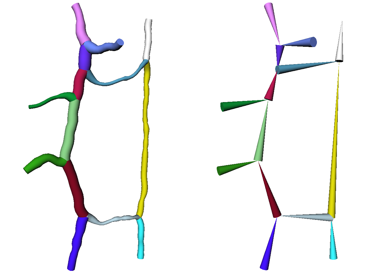
Very simple channel network converted to a HxLineSet and visualised with a HxDisplayLineSet. Both images show the same channel network, the Color Mode of the lines in the HxDisplayLineSet module is set to the first data column (channel index), and Shape is set to Circle. The left image show the network with the Scale Mode of the lines set to the point value data, while the right image shows only the endpoints of the network, with the Scale Mode set to the second column (point number).
NOTES:
- If extracting only the endpoints after processing the network (e.g. with Channel_Network_Process), the connection between the channels can be lost in the resulting HxLineSet.
- Some of the data is constant for each channel (channel index, angle, aspect ratio, length), while others are distinct for each point of each channel (point index in channel, radius).
- The HxLineSet data structure contains, for each data type, one data point per point. So for storing data that is constant along the channel, the structure stores as many copies of that datum as there are points in the channel. It's suboptimal, but c'est la vie.
Connections:
Channel_Network
[required]
The input channel network, of type HxChannelNetwork.
Ports:
Type
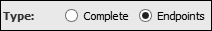
Extract all the points of the channels, or only the endpoints.
Number
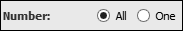
Extract all channels, or just one.
Which

If just one to be extracted, which one.
Point_data

Selects which data to extract for each point. In the output lineset, data columns are named Data0, Data1,Data2, etc. and are ordered in the same way as the tick boxes. Those are:
- Channel
- The channel index, starting at 0. All points of a channel will thus have the same channel index.
- Index
- The index of the point in the channel, starting at 0. Can be useful when looking at channel direction (and debugging).
- Radius
- The value associated to each point (in the context of skeletonization, is the radius of the largest sphere centered at that point and contained in the skeletonized object).
- Angle
- The angle of the channel from a reference direction. Options are set with additional ports.
- Aspect ratio
- The ratio of the length of the channel to its average diameter.
- Length
- The length of the channel, measured by the sum of the distances from adjacent points in the channels.
Angle_reference

Reference direction from which to compute the angle. For instance, if you want to show the verticality of the channels, your reference direction would be (0,0,1).
Angle_options
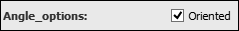
Typically, the channel are not oriented, i.e. the ordering of the points is not physically relevant, which means that angles will be between 0° and 90°, a 180° angle will be the same as 0°, 135° the same as 45°.
But if the Oriented box is ticked, that won't happen, angles are between 0° and 180°.
Action button
Push the button to start the computation.
Commands:
Additional options can be accessed when typing in the console Channel_Network_To_Lines COMMAND_NAME. Typing the command again usually reverts back to original settings.
verbose
Displays timing and other information after the computation. Retype to hide info.
create
Runs the computation. Returns the name of the output, so it can be used in a script, such as set RESULT [Channel_Network_To_Lines create].